LARGE AIR COOLED VRF SYSTEMS (MULTIPLE APARTMENTS)
Quick View Reference: 4
General
These systems are similar to the larger VRF systems described above, but have larger outdoor units (larger compressors).
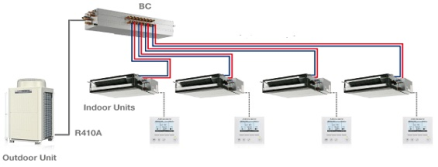
For this report we have considered heat reclaim type only complete with required box controller (BC).
An air cooled VRF (or VRV) air conditioning system’s operation involves:-
- Heat is transferred between the outside ambient air and refrigerant within the VRF outdoor condensing unit.
- Refrigerant is delivered from the condensing units to indoor fan coil units within the building, via a BC. Heat is transferred between the refrigerant within the fan coil unit and the air within the conditioned space.
Refrigerant R410a is currently utilised by all reputable air cooled VRF system manufacturers.
The system arrangement includes:-
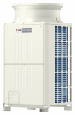
- A single outside condensing unit, consisting of DC/digital scroll compressor/s, condenser coil, DC discharge fan/s and associated electronics.
- Multiple indoor fan coil units, each consisting of an evaporator coil, DC supply fan/s, expansion valve and associated electronics. An extensive range of wall mounted, in-ceiling ducted and other fan coil unit types are available.
- Insulated refrigerant piping connected between the condensing unit and each fan coil unit.
- Associated system control panels and temperature sensors.
Capacity
Each outdoor unit (module) ranges in size, typically 22 to 40 kWr each. To cater for varying capacities multiple modules are used.
Condensers Locations:
- Roof top area
- Level by Level Plant rooms
- Grouped on well ventilated platforms
- Within well ventilated plant rooms
Plant Area on the Roof
Outdoor condensing units can be located in a plant area on the roof. Generally all apartment condensing units associated with a building can be located on the building’s roof except for levels where the height between the apartment and the roof is (typically > 50) but up to >90m. Levels greater than 90 m will require a louvered plant area at low levels.
Refrigerant piping between condensing units located within the roof plant area and apartment fan coil units is installed in shafts within common areas (for future access).
Locating outdoor condensing units on the roof offers the following advantages when compared to locating condensing units in screened plant areas on each level:-
- The potential for noise transfer from the condensing units to adjacent apartments is reduced.
Locating outdoor condensing units on the roof has the following disadvantages over locating condensing units in louvred plant areas on each level:-
- Increased capital cost due to an increase in refrigerant piping between outdoor condensing units and indoor fan coil units.
- Vertical refrigerant piping shafts between the lowest apartment level and the roof of each building are required.
- The extent of available roof area for other purposes is decreased
Louvred Plant Area on Each Level
Outdoor condensing units can be located in a louvred plant area on each level of the building adjacent the facade. Generally each condensing unit is located in the same building level plant area as the corresponding apartment.
Refrigerant piping between condensing units located within the plant area and apartment fan coil units is installed within common ceiling voids on each level.
Locating outdoor condensing units within louvred plant areas on each level offers the following advantages over locating condensing units in a louvred plant area on the roof:-
Reduced capital costs due to a reduction in refrigerant piping between outdoor condensing unit and indoor fan coil units.
- Vertical refrigerant piping shafts between the lowest apartment level and the roof of each building are not required.
- The extent of available roof area for other purposes is increased
Locating outdoor condensing units within louvred plant areas on each level has the following disadvantages over locating condensing units in a louvred plant area on the roof:-
Louvred plant areas on each level are required.
- The potential for noise transfer from the condensing units to adjacent apartments is increased.
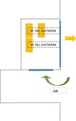
E.g. 1 Building Indent Location (Floor by Floor)
Considerations:
Typically with larger sized units the heat rejection fan can be obtained with a maximum static availability of 60 Pa.
When grouping condensers, it is critical heat discharged via the fan is able to be removed from the air intake otherwise short circuiting occurs and causes condenser failure.
When groups of condensers are staked above each other (floor by floor) in still conditions a heat plume can be created with the effect that higher floor levels air intake temperature is elevated (thus causing condenser failure).
Locating condensers in car parks is not recommended due to short circulating issues.
Provision of an isolator per unit is required
Condensate will occur. Provide means to remove
Mount units off floor to limit corrosion.
Provide bi-gold or similar treatment to condenser coils when located in salt areas or in high pollution areas.
Pipework Limitations
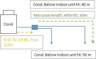
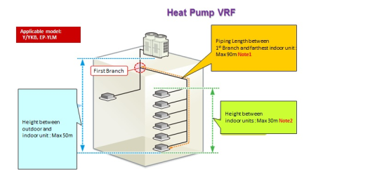
Air cooled VRF systems have extended maximum refrigerant piping length and vertical separation capabilities between indoor and outdoor units when compared to other air cooled refrigerant only based systems such as single or small multi-split systems.
Typical limitations
| Piping in the figure | Max. length [m] | ||
| PUHY-P***YJM | PUHY-P***YLM | ||
| A+B+C+D+E+a+b+c+d+e+f+g | 1000 | 1000 | |
| A+C+D+E+g / A+B+c | 165 (Equivalent length : 190) | 165 (Equivalent length : 190) | |
| C+D+E+g / B+c | 40 | 40 (*3) | |
| H | 50 (*1) | 50 (*1) | |
| H’ | 40 (*2) | 40 (*2) | |
| h1 | 15 | 15 (*4) | |
| *1. | 90m is available depending on the model and installation conditions. | ||
| *2. | 60m is available depending on the model and installation conditions. | ||
| *3. | 90m is available. When the piping length exceeds 40m, use one size larger liquid pipe starting with the section of piping where 40m is exceeded and all piping after that point. In the figure above, if the piping labeled “E” exceeds 40 meters (but does not exceed 90 meters), increase the size of the liquid piping labeled E, f, and g by one size. | ||
| *4. | 30m is available. If the height difference between indoor units exceeds 15 meters (but does not exceed 30 meters), use one-size larger pipes for indoor unit liquid pipes. In the figure above, if “h1” exceeds 15 meters, increase the size of the liquid piping labeled C, D, E, d, e, f, and g by one size. | ||
Note: Each pipe bend reduces the available length of pipework
Pipework should be run in individual apartments space (for that apartments AC condenser) or in common areas.
The use of these modules (single or multiple) allows for entire building floors to be served from one condenser location.
Limitations on condensing unit capacity and refrigeration volume in accordance with AS 1677.2:1998 Refrigerating Systems – Safety Requirements for Fixed Applications must be considered.
Controls
Apartment air conditioning control functionalities are managed at a control panel associated with each fan coil unit. However each control panel is also connected to a BMCS which operates the condensers and BC based on cooling or heating demand from each fan coil unit.
See Ownership & Billing, below for more control requirements.
Heating & Cooling: Two systems types are available, namely; cooling only and reverse cycle.
Cooling Only
Cooling only systems are suitable where heating of a conditioned space is not required. This is generally not the case.
Reverse Cycle
Reverse cycle systems have the ability to cool and heat, however only simultaneous cooling or simultaneous heating can be accommodated by all fan coil units connected to a single condensing unit. Therefore all rooms within an apartment served by a reverse cycle system can only be provided with either cooling or heating at any one time.
Heat Recovery
Heat recovery systems utilise branch selector units within the refrigerant piping to allow independent cooling and/or heating from any fan coil unit connected to a single condensing unit. Therefore individual rooms within an apartment can be provided with either cooling or heating at any one time
Ownership & Billing: Refer to Large VRF Systems – Multiple Apartments
