INTRODUCTION
This post provides typical design advice for apartment AC systems. The author takes no responsibility for use of this post by any persons.
Author: Jorgen Knox (e: jorgenk@knoxadv.com.au, t: 02 800 33 100)
Status: For review and comment, only
Date: 23/09/2016
Load Estimation
The correct load assessment of an apartment is critical to the success of the air conditioning system. The following loads are typically considered for air conditioning apartment design.
Note: The data below is for information only. No warranty, what so ever, is provided or implied.
The following diagram summarises the incident loads onto a typical air conditioning system.

Design Conditions
Typical room conditions: 24 Deg C and 55% RH
External: As per C.A.M.E.L
Windows Allow for the shading effect of fixed external building elements, (balconies, etc.).
Discuss in detail with the Client shading effect of blinds/drapes. Provide advice regarding the impact of blinds on the cooling load i.e. an apartment owner may be very disappointed if the curtains need to be closed for the AC unit to achieve design internal temperatures.
On West Facing windows consider performance glazing typically U Value = 3.5, SC = 0.53. Check supply air l/s/m2 and adjust glazing until reasonable air flow achieved.
Walls: Consider heat gain through outside walls.
[Note: Recalculate U values for walls as building height increases as Outside Surface Air Films Surface Resistivity reduces.]
Ceiling/Roof: Consider heat gain to ceiling space from fabric and lights.
Thermal Mass: Typically C.A.M.E.L thermal mass used for residential is 350 kg/m3.
Shading: Consider the potential shading effect of adjacent buildings.
Do not normally allow for any shading effect due to planting, (trees), which is often transient.
Infiltration:
Allow for infiltration in cooling loads. In well sealed modern apartment buildings allow the diversified exhaust flow rate as the infiltration load. In C.A.M.E.L this can be entered as a fixed outside air low equal to the diversified exhaust flow rate.
Ceiling Void:
Consider infiltration of out side air to ceiling void if used as a return air plenum. Where practical utilise ducted return air . Ensure that an additional allowance is made in the cooling load to offset infiltration to the ceiling void.
Do not use a roof void as a return air plenum. Roof voids are prone to ingress of out side air. Always ensure that return air is ducted through roof voids and the duct work appropriately insulated. Check application of roof insulation, ie located on underside of roof sheet, or on top of the ceiling.
Make Up Air:
Make up air for exhaust systems is a code requirement. Many buildings are still built with no means of make up air.
No Make up Air – This does not comply with NCC reference standard AS1668.2 (2012).
Make up air (as per infiltration) is a load on the air conditioning system.
Note: Modern building becoming more airtight. Make up air via purpose designed, acoustically treated air intake for controlled infiltration for make-up to kitchen, laundry and toilet exhaust systems is required.
Refer to post Apartment Air Flows
Partition Loads: Consider fabric gain from unoccupied apartment adjacent, above and below.
[Typically allow for half temperature difference between apartments]
Reflectance: Increase overall safety factor by 5% if adjacent areas are highly reflective (ocean, harbour, clad building facades, etc.)
Heat Loads
Under take C.A.M.E.L heat loads for all projects. Consider the following:
Q INTERNAL
Misc. Equipment:
- TV & Audio Equipment:
Consider 200W [Seek client confirmation].
- Fridge:
Consider 150W [Seek client confirmation].
- Cooker:
Consider 150W [Seek client confirmation].
Misc. Equipment Summary: With diversity consider 545 Watts for internal loads for appliances.
Lights:
Consider 5 to 9 w/m2. Incorporate upward and downward components and light ballasts and transformers.
Fan: Make allowance for fan gain. Consider Pa with say 120 pa (bulk head unit) or say 250 Pa (ducted unit) in CAMEL settings
People:
Allow for the following people in a zoned apartment:
- Master bedroom – 2 people
- All other bedrooms – 1 person
- Living areas – Sum of people in master bedroom and other bedrooms plus 1
Allow for the following people in a fully air conditioned apartment:
- All bedrooms – 1 person
- Living area – 2 people
Each person will emit 150W (75 sensible and 75 latent approximately). This is typical for a seated/standing activity.
Q EXHAUSTS
Toilet Exhaust:
- Allow Outside air make up to full exhaust quantity for 24 hour toilet exhaust systems.
- Allow outside air make up to 50% full exhaust quantity if intermittent toilet exhaust quantity.
Minimum air flow rates: 25 l/s
Laundry Exhaust:
- Allow Outside air make up to full exhaust quantity for 24 hour laundry exhaust systems.
- Allow outside air make up to 50% full exhaust quantity if intermittent laundry exhaust quantity.
Minimum air flow rates: 40 l/s (dependant on dryer requirements).
Kitchen Exhaust:
- Allow Outside air make up to full exhaust quantity for 24 hour kitchen exhaust systems.
- Allow outside air make up to 50% full exhaust quantity if intermittent kitchen exhaust quantity.
- Air flow rate depends on hood selected (120 l/s is a small hood air flow)
Exhaust Summary: Allowing all systems to run continuously will result in oversized air conditioning, for the majority of operating times. Based on the exhaust flow rates above a diversified flow rate of 60 l/s should be considered.
Kitchen Hood: 120 l/s x 0.5 = 60 l/s
Laundry: 40 l/s x 0.5 = 20 l/s
Bathroom 1: 25 l/s x 0.5 = 12 l/s
Bathroom 2: 25 l/s * 0 = 0 l/s
Diversified Total: circa 60 l/s
Note: On warm or cold days when all systems are operating room conditions will not be maintained.
Safety Factors:
Typical Safety Factors s:
- Supply Duct Leakage & Heat gain: 5%
- Return Air Heat Gain: 5%
- Overall Safety Factor: 20% (This allows for AC systems to bring an apartments temperature down, if left for an extended period in summer)
Unit Selection
The selected air conditioning unit must be selected under the following minimum conditions:
- Coil Face Velocity: NO MORE than 2.5m/s based on air conditioning unit ‘fast’ speed at minimum external static, i.e. clean filter condition. Check with unit manufacturer the maximum air flow at which the unit is rated to operate without condensate carryover off the coil.
- Off coil temperature: The aim here is to have the supply air temperature, thus supply air device temperature above the dew point of the air to avoid condensation. Typically a minimum 0f 11.5 Deg C is used.
- External Static: Based on calculated external static. Check static at all speeds to ensure over supply is not occurring (coil velocity < 2.5m/s).
- Fan Speed: Typically select units on medium fan speed.
- Acoustics: Typically assess on fast speed.
Air Conditioning Unit Location
Ensure that the manufacturer’s recommendations are sought and followed.
The location of the air conditioning unit within the apartment is important. The location must be noise tolerant, provide easy access and enable ductwork etc. to be efficiently circulated.
Often the ceiling below an AC unit is part of a destruction zone (i.e. allows for easy removal of the ceiling should the AC unit need to be fully removed).
Typically, ceiling mounted units are installed in the entrance lobby, above wet areas or kitchens in each apartment.
Location over wet areas and kitchens is often done due to tolerance in ceiling heights. Extreme co-ordination with hydraulic services is generally the draw back in this instance.
Where ceiling access is not possible units can be cupboard located.
Condensate Removal
Ensure that the manufacturer’s recommendations are sought and followed.
Establish the following requirements from the unit manufacturer:
- Grade required to ensure that built-in condensate tray operates effectively;
- Ensure AC units have integral safety trays (if not provide safety tray to capture leaks/condensate).
- If condensate removal pump cannot be avoided, ensure that traps, sump, float switch, etc are all correctly installed.
Note: Ceiling mounted units in particular are designed to very close tolerances in order to achieve minimal room ceiling heights. Some draw through units are built with the fan scroll almost sitting in the drain tray. As a consequence there is a tendency for pooled condensate to be lifted sucked out off the tray through the fan and in to the supply air duct work.
Wherever possible, avoid pumped condensate removal. Ensure that adequate fall is available for a gravity drained condensate system wherever possible.
If pumps are required to be adopted, use pumps factory fitted by the manufacturer. Some pumps operate on extremely fine tolerances and are very difficult to install and commission on site.
Where possible, provide all air conditioning units with drained and insulated safety trays.
Ensure condensate pipe work is correctly installed with no sags. Use copper pipe work where possible at a minimum 22mm Dia.
Ensure condensate pipe work discharges over trapped tundish. Tundish must be visible to occupants.
Architect Note: An indoor AC unit must be positioned to allow for condensate removal. This means considering where the condensate pipework will fall gradually to. Condensate pipework cannot be routed in an up/down fashion. A window or door, in the path between AC unit and tundish, will prevent condensate removal i.e. pipework cannot pass through these elements in a continuous sloped manner.
[Do not connect directly into sewer pipe work].
Ductwork
Refer to separate Ductwork post (In Progress) for guidance on appropriate design criteria. Typically, ductwork velocities to not exceed 5m/s.
KAE recommends that solid ductwork be installed except for final connections to grilles etc. Max flex length to be 3m.
All rigid ductwork to be insulated with minimum 25mm thick insulation. Insulation shall generally be applied internally for acoustic purposes.
All flexible ductwork to be supplied with factory installed internal 25mm insulation. All flexible ductwork to be 2 hour fire rated.
Bulk Heads
When advising the Architect of clear internal bulk head sizes, allow for ductwork supports, insulation and connection to grilles with OBD’s.
Access
Adequate access is required for maintenance of the unit and to adjust air flows. Where possible, sufficient access should be provided to allow removal of the unit.
As a minimum access to the following is generally required:
- Electrical control panel;
- Drain connection, trap, site glass;
- Fan;
- Compressor, (water cooled packaged unit);
- Filter Removal;
- Motorised damper maintenance and motor replacement.
Where possible, provide permanent access to duct dampers to facilitate readjustment of air flows post commissioning. Group dampers to minimise the number of access opening required.
Noise
Comply with AS2107
The following minimum acoustic treatments are typical:
- 50mm internal insulation 3 meters up/down stream of AC unit;
- Line internally casings housing compressor units;
- Consider acoustic splitters at each grille or low velocity ductwork at grille;
- Internally insulate supply and return air header boxes;
- Provide acoustic elbow on return air grille to ceiling plenum;
- Provide insulated return air plenum;
- Advise Architect to specify acoustic door seals for air conditioning cupboards;
- Allow to internally insulate air conditioning cupboards where directed by Project Acoustic Consultant;
- Low ductwork and grille velocities
Outside Air Requirements
Outside air supply is required to comply with AS1668.2
Typically 10l/s per person. With filtration this can be reduced to 7.5 l/s per person
For many apartments outside air is not ducted to the air conditioning units. The NCC/BCA, section F allows us to consider openable doors and windows as a means of providing outside air. Typically a operable opening must be sized at 5% of the room floor area, for compliance with Part F of the NCC (Natural Ventilation).
The NCC provides guidance as to what area of a window is considered as operable. In summary, the whole window, is considered as operable (as apposed to just the physically open part of a window.

[Note/Advise to Client: Opening of doors/windows will result in loss of conditions].
In cases where opening of the doors or windows would mean that internal noise levels are exceeded then an alternative method of introducing outside air will be required:
ALT 1: Acoustic Air Intake to outside
ALT 2a: Provide a lobby outside air supply and introduce air via door under or via fire dampered transfer duct.
ALT 2b: Similar to 2a, above, where the development requires stair pressurisation the associated relief air shaft can be utilised to deliver outside air to each floor. Air to each apartment is then via fire dampered air intake (typically a 300 x 200 intumescent fire damper with acoustic flexible is utilised).
Part Schematic (showing Corridor Outside Air System)
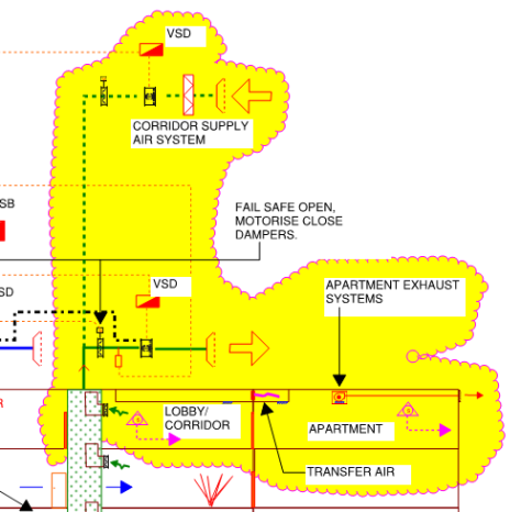
ALT 3: Provide ducted outside air shaft within apartments (often used in hotel applications)
[Note: Remember to make an appropriate additional allowance on the unit cooling capacity in order to offset this additional load].
Zoning
Many apartments require the ability to zone the air conditioning, e.g. only condition the bedrooms of an apartment and not the living areas, or vice versa. This type of system is generally termed a ‘day/night change over system’.
Control of the system is achieved by installing day/night motorised zone shut-off dampers which the owner can operate.
Zoning typically allows for the air conditioning unit to be down sized. This is achieved by sizing the unit on the peak load for the day zone only.
[Note: It is essential to point out to the client that loss of conditions will occur on hot days if all zones are operating simultaneously].
Care must be taken to avoid excessive air supply with zoning. If zones are of different sizes and loads, the smaller zone may be over supplied with air. This can be overcome by ‘dumping’ excess air to additional areas outside of the zone.
Ideally a controller is provided in master bedroom and in the day area ( 2 off controllers). Operation of either controller, will ensure that room will control the supply air temperature.
Supply Air Devices
Refer to Ductwork post (In Progress) of this manual for register and grille selection criteria.
Typically grilles are located within fixed ceilings i.e. no access. Suitable allowance for commissioning is required. This is typically achieved by two methods:
(i) Install VCD in ductwork with access panel in ceiling.
(ii) Install OBD behind face of grille with adjustment from face of grille
Where OBD’s are installed at face of the register, ensure ductwork velocity is < 4m/s.
Commissioning
It is often very difficult to arrange access to apartments once they are handed over and occupied. It is generally not possible to gain sufficient access in order to adjust the water balance after hand over, particularly if floor branch balancing valves are not used. It is therefore vital that each apartment is fully commissioned, tested, and documented as such, prior to final handover.
Comprehensive testing of the system is required to be undertaken, including reconciliation of each element’s performance with the original design. Sufficient testing should be undertaken to reliably verify performance of the following elements:
- Air conditioning unit output;
- Air balance;
- Transmission loss on supply air duct work system, (air leakage and temperature pick up);
- Infiltration through ceiling void;
- Controls operation;
- Condensate drain operation.
Testing of apartment’s systems is difficult due to space constraints, so results are often found to be inconsistent. Each test should be verified by an alternative means, eg measure airflow by the following methods until a consistent result is obtained (i) Balometer or anemometer scan of register; (ii) Differential pressure across unit and reconcile with manufacturers fan curve.
The level of testing to be undertaken on each apartment should be clearly detailed in the tender documentation and adequate allowance built in to the Tenderer’s proposal. In practice, time constraints often do not allow comprehensive testing to be undertaken on each apartment. In this case, KAE recommends that at least one apartment of each layout type, and AC unit type, be fully tested to ensure; design parameters are correct, air conditioning unit capacities are correct and in accordance with manufactures data. The remainder of the apartments must be fully commissioned in terms of condenser water flow rate and air flow rates.
The main items required to be tested and witnessed are air flow; water flow; cooling capacity:
Air Flow
Assess and verify the supply air flow by a number of different methods, including at least 2 of the following:
- Balometer or anemometer scan of register;
- Anemometer scan of return air opening to the air conditioning unit;
- Differential pressure across unit and reconcile with manufacturers fan curve.
[Note: That it is normally not possible to undertake a reliable pitot tube traverse due to the lack of a suitable duct section.]
Cooling Capacity
This is best calculated local to the unit by measuring total air flow and air on and air off dry and wet bulb temperatures. Also measure refrigeration pressures, compressor amps and verify by reference to the manufacturer’s data.
Provide access and duct tapings to allow for temperature measurement.
Water Flow
Commissioning valves (complete with pressure tapings), easily accessible must be installed on all pipe work local to air conditioning units. Also install and undertake balance on floor branch valves to facilitate rebalancing subsequent to hand over if required.
Control Sensor Locations
The location of control temperature sensors is an important consideration.
Do not install: In direct sunlight, or under the influence of local equipment heat gains;
Install in: A representative area, typically 1.5m above the floor;
Number:
Typically one sensor/control panel is provided. Where two zones are installed consider master control panel/temperature sensor. Activation of either panel initiates its associated sensor.
[Seek client approval for more than one control panel, due to expense]
